Stomp Box
This project didn’t really work, but it was interesting. And you only really learn when you fail.
What is it?
A wooden box you stamp on to make a percussive bass-y sound, because I want to sound just like Seasick Steve when I play the guitar. They can be amplified or not amplified, but this article is about building an amplified one.
The plan
*------------*
|  Mic in a  |----------| Low Pass Filter |-----------| Amplifier |----- etc
|    box     |
*------------*
Attempt 1
A small box built from some wood I found in a skip. Inside it, an old speaker, wired together with the simplest possible low-pass filter, which should make the sound a little bassier.
   +        R
\ | -----\/\/\/------*---------
| |                  = C       Output
/ | -----------------*---------
   -
Any speaker will act as a rudimentary microphone, because they’re both a coil stuck on a cone next to a magnet (see speaker design and microphone design).
I tried to wire this speaker and low-pass filter through my pre-amp (advertised as having “high impedance” inputs, probably \(\sim 1 k\Omega \). The low-pass filter does make an impact - the sound is noticably deeper with it - but with or without it there is a lot of white noise, probably because a bit of old speaker doesn’t provide enough signal.
Attempt 2
The same small box, built from skip-wood, but now with a PCB mounted electret microphone and a wonderfully simple circuit:
    +---------------------------- battery +ve (3 to 12 Volts)
    |
   2k2 R1
    |
    o---------- 10uF ------o----- output
    |+                     |
 CAPSULE                  10k R2
    |-                     |
    +----------------------o----- GND, and battery -ve
This gives a much deeper background noise but still far too much of it - perhaps because the output impedance is basically determined by R2, so is probably around 10 times higher than the input impedance of my pre-amp, which is a bad thing.
Attempt 3
Time to try an op amp. There’s a wealth of information about these all over the internet. I’ve chosen this one because it’s simple enough for me to understand the entire thing, and because I had an LM358 hanging around from another failed electronics project from years ago (there’s a theme here).

I’ve added:
- A \( 100\Omega \) resistor and a \( 100k\Omega \) log pot, both in series with the output. Without the \( 100\Omega \) resistor, there was far too much gain with headphones and the op-amp would oscillate wildly, the \( 100k\Omega \) pot acts as a volume control.
- Battery protection diode, power-on LED, and switch.
Adding an active low pass
It’s pretty easy to add a low pass filter to a standard inverting amplifier circuit like the one above - you add a capacitor C in parallel with the resistor R on the feedback loop between the inverting input and the output. The larger the impedance, the higher the gain. At high frequencies, the impedance of the capacitor is very high so the impedance of R and C in parallel is close to C, giving a lot of gain. At lower frequencies the impedance of R and C is close to R, since the impedance of C is so high, giving less gain.
At \( 86k\Omega \) and \( 15nF \) the cut-off is about 123Hz, which is near-enough an octave below middle C.
Making it bassier
The de-coupling capacitors as they stand (\( 10\mu F \) between the microphone and the operational amplifier, and \( 220\mu F \) between the op amp and the output) form high pass filters. For example at 20Hz, which is the lowest frequency my microphone claims to be able to pick up, the resistance of the \( 10\mu F \) capacitor is
\[X_f = (2 * pi * f * C)^-1 ~= 800 \Omega\]which approaches the vlaue of the \( 1k\Omega \) resistor it’s in series with.
Just to be sure, raise these capacitors, \( 10\mu \rightarrow 220\mu \) and \( 220\mu \rightarrow 1000\mu \).
Decoration*
*Not by me.
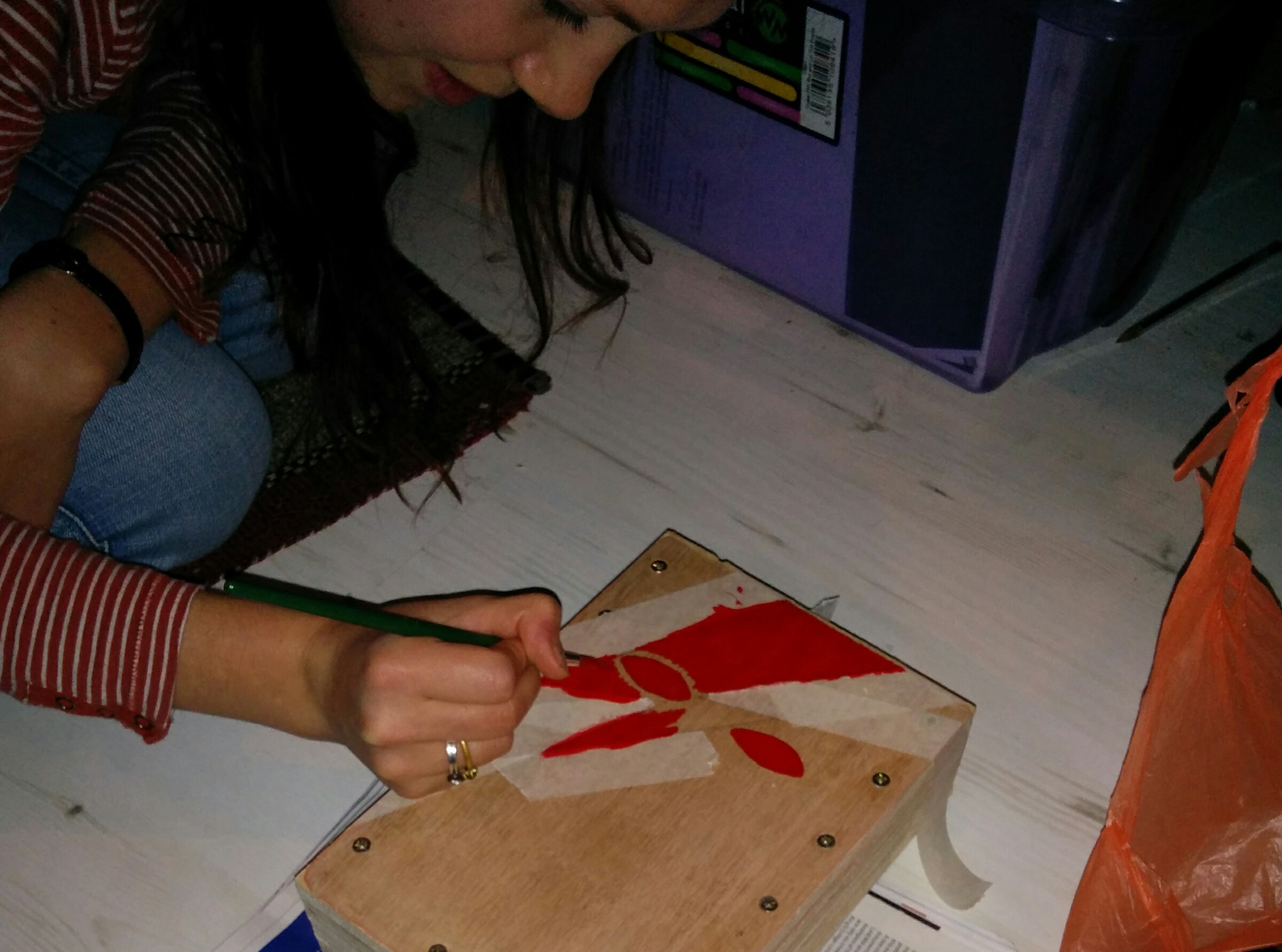 .
.
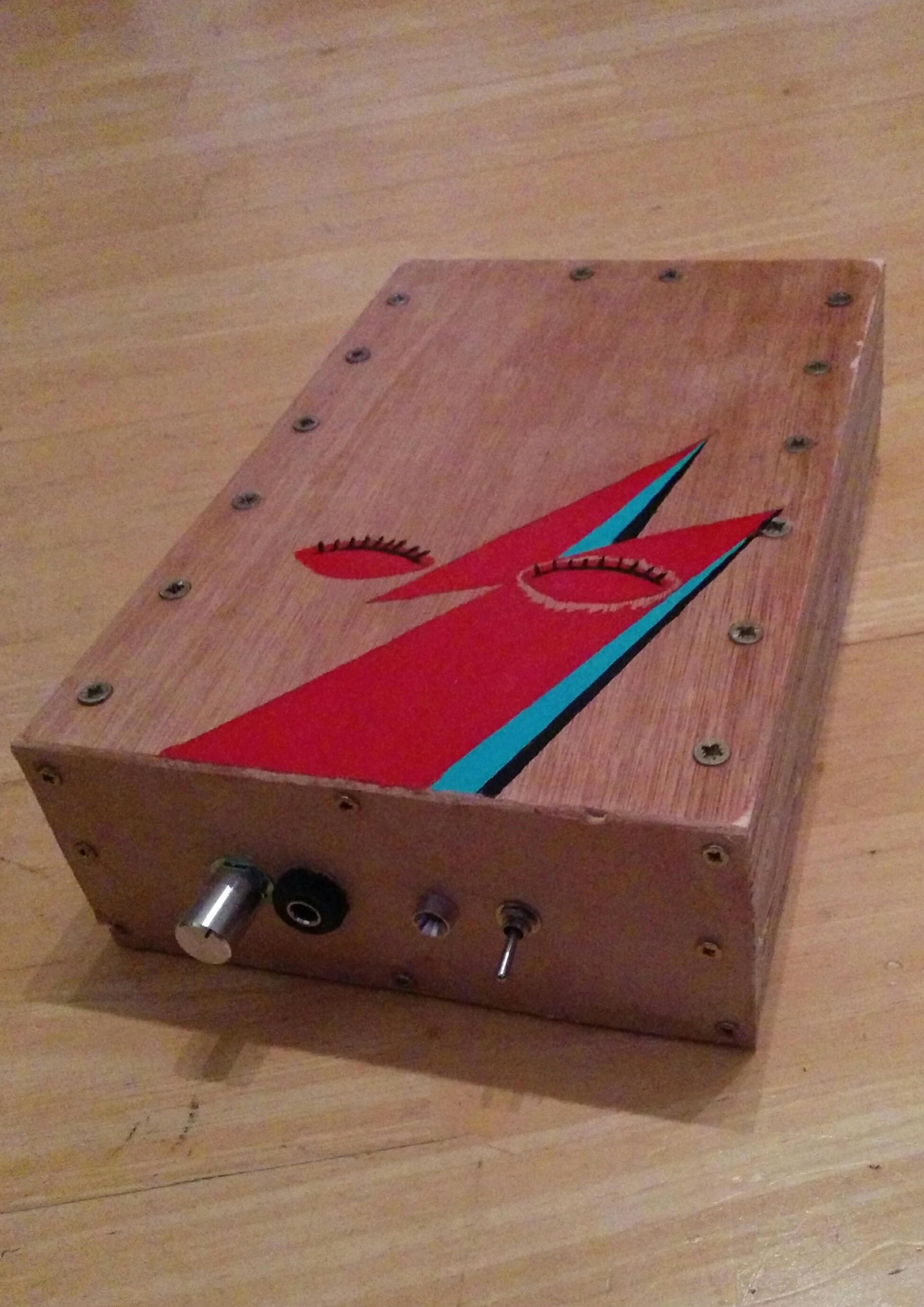
Finished item
I realised by this point it was never going to sound great, so the front is pretty awful.
Next attempt
Perhaps use Bass pickups in an isolated box?